|
|

TerraGraphics
Make a simple UTP CAT5 Ethernet crossover
|
How can I connect two Ethernet adapters without a hub
(or two hubs to each other)?
I read dozens of descriptions of how to do this and was still confused.
Here's an easy way. We'll modify an RJ45 female to female coupler
instead of making a special cable. This requires no tools and
saves you the trouble of deciding how long you want your crossover cable.
Step 1
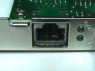
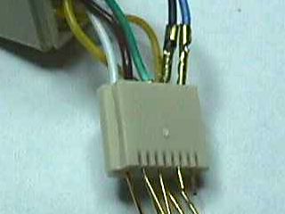
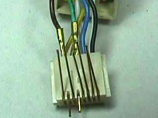
To find out which pins we need to change, we can look at an old 10/100
Ethernet adapter. Notice I've positioned it so the locking tab of
the plug would be at the top and we can see the contacts at the
bottom. I'll call the contacts pins. At the right there are three pins
and some space to their left and then another pin. Counting from the
right, these are pins 1, 2, 3, empty positions 4 and 5, and then pin 6.
Positions 7 and 8 are empty.
Ethernet uses pairs of these pins. Pins 1 and 2 comprise a pair and pins 3
and 6 are another pair. 1000 Mb ethernet uses all the pins.
Pins 7 and 8 are a pair and pins 5 and 4 are a pair.
Step 2
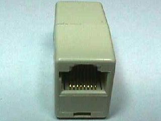
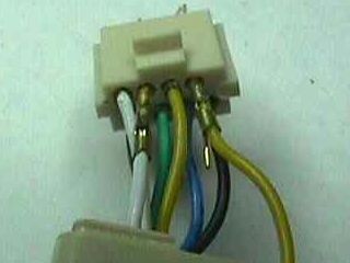
Looking at an RJ45 female to female coupler in the same orientation shows
the pins in the same positions. This may seem obvious but bare with me.
If you connect the adapter above to this coupler, the cable would
connect pin 1 to pin 1, pin 2 to pin 2, etc. It's called a straight
through cable. So looking at the coupling, pin 1 is on the right - it's
always on the right. If you turn the adapter around and look at its other
end, pin 1 is on the right (of course). This means that, as we see it in
this picture, the other end (which we can't see) has pin one on what is
our left as we look at it from here. The wires inside the coupler cross
over from one side of the coupler to the other to reach the corresponding
pin on the other end connecting pin 1 to pin 1, pin 2 to pin 2, etc.
Step 3
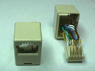
Grasp half the coupler in each hand and try to bend it. The two halves
will pop apart. The wires inside are probably twisted. Turning one half
relative to the other will untwist them so you can pull the halves apart a
little further. We will rewire one half only. Either will do - they
are identical. Ignore the wire colors - they have no meaning.
Doing the next part without damaging the connector can be tricky. The
block that holds the wires must be removed from its case. Look into the
back of one of the halves and gently pull the bundle of wires toward the top
(compressing the eight contact springs). You'll see the block
move up slightly releasing itself from the case. If it
pops out, you are done.
If it does not, you'll see the catch at the bottom release with a click
but, when you let go, it snaps back in place. This is because one or more
of the contact springs has its end embedded in the plastic case. To
release them, plug in a cable. This will push all the contact springs away
from the case. With the cable plugged in, try again to release the block
by pulling the bundle of wires toward the top. You'll have to pull much
harder with the plug inserted but, when you do, the block will pop out.
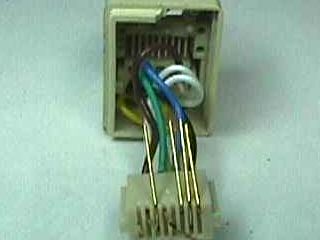
Step 4
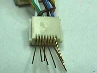
Straighten all the contact wires. Note that each one is bent at two
places where it goes around two corners of the block. You'll need to
unbend these spots (not make a new compensating bend). The contact springs need
to be straight so you can pull them out and put them in again. The
picture shows it done well enough.
Step 5
Remember the pairs?
Pins 1 and 2 are a pair and pins 3 and 6 are a pair. We need to reverse
the pairs. That means, instead of 1 going to 1, etc.:
The 1 and 2 pair at one half will go to the 3 and 6 pair at the other half.
The 3 and 6 pair at one half will go to the 1 and 2 pair at the other half.
To do that, we need to swap pins 1 and 3 and also swap pins 2 and 6.
Pull out pins 1 and 3 as shown and swap them. Notice they are still at
the right (We haven't lost our original orientation.). At first glance
you might think these are pins 1 and 2. Look closer. Pin two is below
and between them. Be sure you get them back in all the way and bend the
contact springs
up over the block so you won't have to worry about these two again.
Remember not to push the
contact springs
flat against the top of the block. They need to
spring away from it to press against the plug when a cable is plugged in.
See the picture at step 3.
Step 6
Flip the coupler over from front to back and swap pins 2 and 6 as
shown.
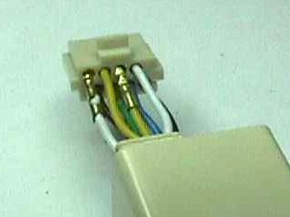
Step 7
With them swapped and the contact springs bent over and the coupler
flipped back to its original position, it will look like this.
Notice that these are the same contact positions we saw in step 1.
Step 8
If all you need is a slow crossover, you can skip ahead, but don't
- we're almost done with a fast crossover. The other pairs are the
pin 7 and 8 pair and the pin 5 and 4 pair. We need to reverse these pairs
too:
The 7 and 8 pair at one half will go to the 5 and 4 pair at the other half.
The 5 and 4 pair at one half will go to the 7 and 8 pair at the other half.
We need to swap pins 7 and 5 and also swap pins 8 and 4.
Flip the coupler over from front to back and swap pins 8 and 4 as
shown.
Bend the contact springs and flip the coupler
back to its original position.
Step 9
Swap pins 7 and 5 as shown and bend them. All the contact springs should
be bent now.

Step 10
Snap the block into the case making sure each contact spring slides into
its slot. Look inside the end you worked on and make sure each contact
spring is in the correct slot. Snap the two halves of the case together.
Twisting them a turn or two might make the wires pull in better.
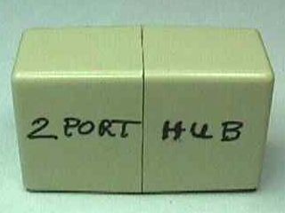
Step 11
Label it now so you don't lose track of which one you modified. Yes, you
have just built a two port Ethernet hub.